
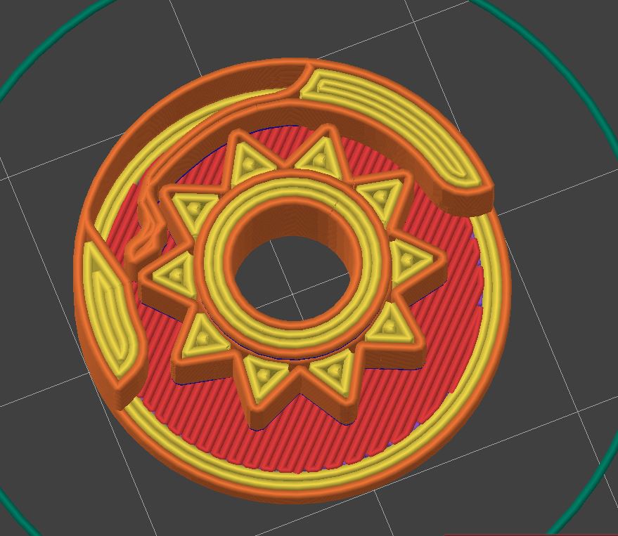
After half a dozen iterations, this was the first reasonably working, acceptable feeling, and good-sounding ratchet mechanism.
allows clockwise rotation blocks counterclockwise rotation
design features:
- allows for a large inner bore (e.g. rotary encoder shaft or 5.2mm screwdriver bit)
- printable with 0.4mm nozzle
- 2cm diameter
- no assembly required. Print in place.
To get a full ratchet: mirror the assembly and add a mechanism/part that pushes one of the springs out. In neutral both leavers are engaged and the ratchet is completely locked.
Btw. Good luck copying it without going through half a dozen of iterations. Going from it barely works to this isn’t easy. For my part: Version 5 was working and close to the final design. It took another 10 rounds to get it usable and from there some more to fine-tune it.
If you consider sharing mechanical design concepts as not in line with the spirit it’s fine but others are likely interested in seeing how things work and takes it as inspiration for their designs.
Go and recreate it. Nobody stops you. Could provide the STL but wouldn’t be worth a lot as this is so dialed (tolerances) that it comes down to the specific printer/extrusion system. There are older revisions with huge tolerances (0.4mm) that work but wear down rapidly. To print this exact version it needs to be capable of printing with 0.23mm gap/tolerance between parts.
Then post the parametrised step file so people can tinker themselves.
That said, if you did all this work and went through all these iterations to make a single ratchet that nobody else can copy then it sounds like you massively wasted your time. I would far prefer something with a tiny bit of assembly to a print-in-place gimmick that takes far more effort. The only way this makes any sense is if you’re making a lot of them.
I guess keep it to yourself in that case.
Watch your attitude.
I think you still somehow assume this is some kind of ad to sell this design for money or I am a jerk for not just publishing it with source files.
Also not everybody spends their time designing and publishing whatever is popular at the moment on Makerworld to collect points/store credit. There is a different world that doesn’t run on Fusion360 source file most people could edit and can design parts with a particular material & print(farm)/process in mind to get the most out of the FFF 3D-printing process.
WaTCh YoUr aTTItude
Lol, you got told your attitude was the problem and you just had to offload that onto me, didn’t you?
It’s your attitude. This post is better off in one of the functional print communities anyways.
Here you go: https://www.thingiverse.com/thing:6595547
v10 should still be 0.4mm tolerances (easy to print) on all sides and working. Otherwise not a great design but enough for you to understand that there are dozens of parameters to tune in such a “simple” mechanism and it is (nearly) impossible to nail it on the first try. Have we started talking about optimizing the force required to break it loose? That’s one more thing that needs to be accounted for.